Instrument lightning protection projects can be implemented based on the following conditions:
When a building is equipped with lightning protection according to GB50057 and has installed instruments, especially those with outdoor signal lines, instrument lightning protection projects can be implemented. This helps prevent outdoor signal lines from attracting lightning into the building, damaging electronic equipment, and posing risks to personal safety.
Instrument lightning protection projects are advisable in factory areas where incidents of personnel being struck by lightning or events endangering safety have occurred.
When regulatory authorities or owners assess that the potential economic losses from lightning events exceed tolerable levels or when the expected risk of lightning events is deemed higher than acceptable, instrument lightning protection projects should be implemented.
If the factory area has experienced lightning strikes with a current intensity of 150kA or above, occurring ≥2 times/year, instrument lightning protection projects can be considered. The frequency and current intensity of lightning strikes can be determined based on local meteorological data or self-conducted measurements.
Authorities with jurisdiction may prescribe the need for lightning protection measures without an assessment.
Instrument SPDs should be maintenance-free and capable of withstanding multiple lightning surge impacts without damage.
The electrical surge protection devices with monitoring functions and corresponding centralized monitoring equipment can be used.
SPDs should undergo batch testing for parameters and performance, with a qualification crtificate. The manufacturer should have simulation equipment for standard surge testing, conducted according to GB/T 18802.21 or manufacturer standards. Units or institutions without equipment for surge testing based on standard waveforms are not qualified for testing.
4mA~20mA signal instruments or other signal types powered by a 24V DC circuit should be equipped with SPDs.
The AC power supply end of DC power supply devices should be equipped with ac power surge protector based on the maximum voltage and rated current values, and the DC output end should be equipped with SPDs.
AC power supply for 4-wire instruments should be equipped with AC power supply SPDs.
Control system network communication should be equipped with SPDs suitable for the connected communication devices in terms of specifications and parameters.
Multiple signal channel SPDs should not be used. 4-wire instruments with DC power supply, due to similar current values for power and signal, can use dual-channel SPDs.
SPDs should not affect or alter the signal and transmission characteristics of instruments and lines.
Signal SPDs include modular and built-in types. Modular SPDs should use parallel connection.
When the horizontal path length of signal cables laid above outdoor ground exceeds 100m or the vertical height above ground is more than 10m, SPDs should be installed for control-side instruments. Instruments on the control side in the aboveground tank area should also be equipped with SPDs:
Transmitters and other instruments that convert into electrical signals;
Gas detectors and analyzers;
Electrical converters, electrical valve positioners, solenoid valves, electric actuators, and other signal actuator types;
Thermocouples;
Electronic switches;
Relay coils;
Networks and communication equipment;
Other instruments sensitive to lightning surges or with poor tolerance capabilities.
Instruments that may not require SPDs include:
Thermocouples;
Mechanical contact switches, buttons;
Other instruments capable of withstanding lightning surges.
The primary parameters of signal SPDs include:
Maximum continuous operating voltage (Uc): Uc should be greater than the maximum operating voltage of the circuit, with some margin. Typically, for instruments with a rated operating voltage of 24V, Uc = 32V. (Rated operating voltage Un: the optimal voltage for electrical and electronic equipment during normal operation.)
Discharge capacity: In theory, the greater the discharge capacity, the better. Generally, C2: 20kV/10kA and D1: 2.5kA are required. (C2: represents fast rise, with open circuit voltage waveform of 1.2/50μs, short circuit current waveform of 8/20μs, and virtual impedance of 2Ω. D1: represents high energy, with open circuit voltage ≥1kV and current waveform of 10/350μs.)
Line system: 2-wire, 3-wire, or 4-wire.
Explosion-proof requirements: Intrinsic safety explosion-proof Ex ia II C T4~T6 Ga.
Rated operating current (IL): Signal SPDs generally use series installation, and the current continuously flows through the SPD. It should generally not be less than the continuous operating current of the working circuit, otherwise the SPD may overheat and burn out. High-power instruments should pay attention to this parameter.
Voltage protection level (Up): Signal SPDs generally use 2-level protection, with a lower Up value. This parameter generally meets the requirements.
Bandwidth: After the SPD is connected to the line, it may cause attenuation of high-frequency signals. Bandwidth is used to represent this effect. For example, -0.5dB, 10MHz, indicates that the signal will attenuate by 0.5dB at 10MHz. The signal frequency on industrial sites usually does not exceed 40kHz. The bandwidth of the signal SPDs can reach 40MHz, so this parameter is generally not a concern during selection.
Naming Convention of Signal SPDs (T Series Example):
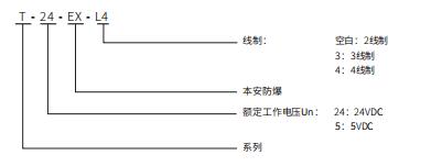
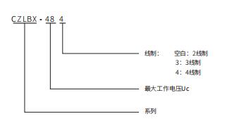
In addition to the reference parameters for signal SPD (Maximum Continuous Operating Voltage Uc, Discharge Capacity, Line Configuration, Explosion-proof), key considerations for SPD used in field instruments include thread specifications. Commonly used thread specifications include 1/2" NPT, M20 X 1.5 (specify thread specification and material when placing an order). When field instruments lack additional interfaces, a three-way interface can be provided.
Naming Convention for SPD Used in Field Instruments:
On-site instruments should avoid installation at the top of equipment or protruding positions that may become flashover objects.
When the installation position of an instrument has the potential to form a flashover object and cannot be moved, the instrument should be installed in a steel plate instrument protection box or protective cover, and the box or cover should be grounded.
On-site instruments should use assembled SPDs, and for instruments inconvenient for assembled SPDs, integrated SPDs can be used. It is advisable to use line-to-line protective SPDs on-site.
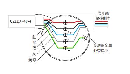
Assembled SPDs should be installed in the vacant line-inlet of the on-site instrument's main body or in an external three-way interface. The external three-way interface should use a sealed threaded installation structure.
The wiring of assembled SPDs should be as short as possible, without bending or excess length.
Explosion-proof SPDs for instrument assembly should not alter the explosion-proof structure and performance of the instrument's main body. Explosion-proof SPDs installed on the instrument's line-inlet should obtain a certificate through the national mandatory product certification (CCC certification) from China's authorized explosion-proof certification institution.
Parallel installation schematic:
Signal SPDs are commonly employed for safeguarding control cabinet ports and are typically connected in series with the signal circuit, mounted on DIN 35mm standard rails. The output end of the SPD serves as the protected terminal, and the equipment being protected should be connected to the SPD's output, without concern for the direction of signal transmission (e.g., AI or AO). The SPD should be installed on the DIN 35mm standard rail before the outdoor cables enter the control room and connect to instruments (safety grids, isolators, I/O, etc.).
Signal SPD Installation Schematic:

The grounding wire of the SPD should be connected to the grounding terminal of the protected equipment's outer shell using a bonding wire, and it should be connected to the earth at the SPD's grounding point.

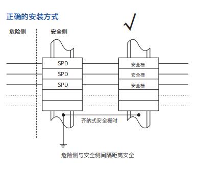
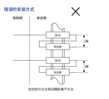
When using SPD to protect safety barriers and connected devices, SPD and safety barriers should be installed on separate rows of different rails to meet the requirement of a 50mm gap between terminals on the hazardous side and the safe side.
Correct Installation Method
Incorrect Installation Method
Control room instrument SPDs should be installed inside cabinets, using rail-type SPDs. The SPD should be mounted on a metal rail, which serves as the grounding busbar. The SPD's grounding rail inside the cabinet should be directly connected to the grounding busbar beneath the cabinet or connected to the protective grounding busbar nearby inside the cabinet. The installation between the SPD's grounding rail and the cabinet should avoid using insulation pads. SPDs and safety barriers can be installed side by side in the same cabinet or separately in different cabinets. When installed in the same cabinet, they should be arranged side by side and not on the same rail. The grounding schematic diagram for the SPD cabinet is as follows:
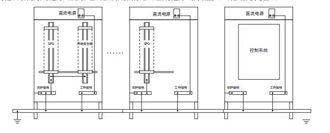
The cabinet body should be connected to the protective grounding busbar inside the cabinet. For instruments, operating equipment, and metal operating tables that need to be grounded, a copper material or hot-dip galvanized flat steel with a cross-sectional area ≥40mm × 4mm (width × thickness) should be laid along the power cable path as the grounding busbar. The grounding of the operating table should be connected to the grounding busbar nearby.
The grounding connection should use insulated multi-strand copper core wires with the following cross-sectional areas:
Grounding wire for a single instrument or on-site instrument: 1.5mm² to 2.5mm²;
Connection wire between busbars or grounding busbars inside the cabinet: 2.5mm² to 6.0mm²;
Connection wire between the cabinet and grounding busbar: 6.0mm² to 16mm².
The outer appearance of all grounding connection wires should be green or yellow-green alternating.
The metal casing of field instruments should be connected to the mounting bracket via grounding screws. The metal casing of mounting brackets, instrument protection boxes, junction boxes, and cabinet should be connected to electrical grounding facilities nearby or connected to the grounded metal body. Reliable conductive objects such as instrument protection steel pipes, metal brackets, metal guardrails, metal troughs, and metal structures can be used as segments of the grounding connection. Instruments, equipment, instrument boxes, brackets, etc., that need to be grounded can be connected in series, with a recommended quantity of ≤3.
For 3-wire-ground protection-type SPD, the grounding connection wire should be connected to the grounding terminal inside the instrument. For line-line protection-type SPD, grounding is not advisable. Instruments mounted on the top of non-metallic equipment should be grounded nearby.
When the horizontal path length of the field bus line above the ground is greater than 100m or the vertical height above the ground is greater than 10m, SPD should be installed for field bus instruments, controller ends, and electronic or intelligent bus branch device ports.
Schematic diagram of field bus instrument SPD configuration:
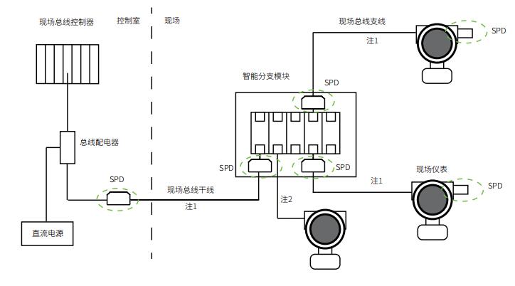
In the diagram: Note 1 indicates that if the horizontal path length of the field bus line laid on the ground is greater than 100m or the vertical height above the ground is greater than 10m, SPD should be installed for instruments; Note 2 indicates that if the field bus line does not meet these conditions, instruments do not require SPD installation.
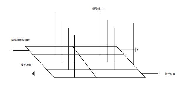
The grounding system for control room instruments should adopt a mesh structure and can be used for various rooms with instruments. The grounding systems for protective grounding, working grounding, intrinsic safety grounding, shielding grounding, electrostatic grounding, SPD grounding, etc., in the control room should be connected to a unified mesh structure grounding system nearby. The mesh structure grounding system should not differentiate between grounding types. The mesh structure should be formed by connecting multiple grounding bars into a network: Grounding bars should be arranged based on the layout of instrument cabinets or operating tables to all cabinets or tables under the raised floor, cable trenches, or suitable spaces. The grounding network for two or more cabinets should be connected at both ends and in the middle, with a grid row and column spacing of ≤5m or a single mesh perimeter of ≤20m.
Mesh Structure Schematic Diagram:
The grounding wire for instrument AC power supply should adopt the TN-S system. The grounding wire (PE wire) from the supply point system should be connected to a grounding busbar inside the instrument distribution cabinet. The mesh structure grounding bar and the outer shell of the distribution cabinet should be connected to the grounding busbar inside the cabinet using multi-stranded copper wires with a cross-sectional area of ≥16mm² and 6mm², respectively.
Working Grounding: Grounding required for the normal operation of instruments and controls.
Protective Grounding: Grounding for the protection of instruments and personal safety, also known as safety grounding.
Intrinsic Safety Grounding: Grounding required for the normal operation of intrinsic safety instruments (such as Zener barrier grounding, negative pole of shunt diode, etc.).
Shielding Grounding: Grounding to avoid interference from electromagnetic fields on instruments and signals.
Lightning Protection Grounding: Grounding to dissipate lightning currents, required for the normal operation of SPD.
Static Electricity Grounding: Grounding to prevent the accumulation of static electricity.