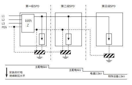
The installation level of SPD depends on the classification of lightning protection zones and the withstand voltage requirements of the protected equipment. Low-voltage power systems and electronic information systems may require the installation of multiple levels of SPD to gradually reduce lightning transient overvoltage and transient overvoltage and energy within the system until the safety and immunity requirements of the protected equipment are met. There are certain principles to be followed between different levels of SPD to ensure energy coordination and operational performance.
Illustration of SPD Graded Protection:

Classification of buildings according to lightning protection requirements based on their importance, usage nature and value, likelihood of lightning accidents, and consequences:
Power System Lightning Protection Levels:
Level A
National-level data centers, national-level communication hubs, top-level and first-level financial facilities, large and medium-sized airports, national-level and provincial-level broadcasting and television centers, hub ports, railway hub stations, electronic information systems of important urban public utilities such as provincial-level water, electricity, gas, and heat facilities.
Level-one security units, such as closed-circuit television surveillance and alarm systems for national-level cultural relics and archives.
Electronic medical equipment in level-three hospitals.
Level B
Medium-sized data centers, second-level financial facilities, medium-sized communication hubs, mobile communication base stations, large sports stadiums/arenas, small airports, large ports, electronic information systems in large train stations.
Level-two security units, such as closed-circuit television surveillance and alarm systems for provincial-level cultural relics and archives.
Electronic information systems for radar stations, microwave stations, highway monitoring, and toll systems.
Electronic medical equipment in level-two hospitals.
Electronic information systems in five-star and higher-rated hotels.
Level C
Third-level financial facilities, electronic information systems in small communication hubs.
Large and medium-sized cable TV systems.
Electronic information systems in four-star and lower-rated hotels.
Level D
General-purpose electronic information systems requiring protection, excluding those in levels A, B, and C.
Recommended values for the surge current and nominal discharge current parameters for SPDs used in power line circuits should comply with the provisions in the following table:

Note: The grading of SPD should be determined based on factors such as protection distance, length of SPD connecting wires, and withstand voltage rating of the protected equipment.
The main relevant parameters for the selection of power SPD are as follows:
Maximum Continuous Operating Voltage (Uc): It refers to the maximum effective value of alternating voltage or direct voltage that can be continuously applied to the protective mode of the SPD. It is also known as the maximum operating voltage.
Under normal system operation, the SPD needs to be in a high impedance (open circuit) state. Therefore, the Uc value of the SPD must be higher than the maximum continuous operating voltage that may occur in the system. Otherwise, there will be a continuous current flowing through the SPD, leading to damage to the SPD before the surge arrives, and even causing fire accidents.
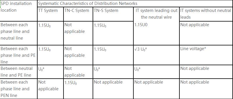
For the selection of Uc, the GB 50343 standard recommends the following:

Note:
Values marked with * represent the worst-case scenario under fault conditions, so the 15% allowable error does not need to be taken into account.
U0 is the nominal voltage between phase and neutral in low-voltage systems, i.e., the phase voltage is 220V.
This table is applicable to SPD products that comply with the GB 18802 standard.
Here, it is important to note the difference between phase voltage and line voltage. For example, in a 220/380VAC voltage system, the phase voltage (L-N) is 220VAC, and the line voltage (L-L) is 380VAC. Power SPDs are generally installed between L-N or L-PE, so the Uc value should be compared with the phase voltage U0. In practical applications, some margin is usually left for the Uc value. Different countries have different power grid quality conditions. In developed European countries with stable power grids, the margin for Uc is smaller, and Uc: 275VAC is commonly selected. In China, the power grid quality is generally lower, so a larger margin for Uc is required, and Uc: 385VAC is more common.
The discharge capacity is a core performance indicator of the SPD. The instantaneous current surge is highly destructive, and not only the internal components of the SPD need to withstand it, but the overall SPD must also be able to withstand it. In theory, a higher discharge capacity is better, but the selection is usually based on the importance level of the protected system and the installation location of the SPD.
The parameters for the discharge capacity of SPD are as follows:
Nominal Discharge Current (In): The peak value of the 8/20μs current waveform passing through the SPD, which the SPD can withstand at least 10 times.
Maximum Discharge Current (Imax): The peak value of the 8/20μs current waveform passing through the SPD, which the SPD can withstand at least once.
Impulse Discharge Current (Iimp): The current waveform that passes through the SPD with the specified charge and energy within a specified time, typically a 10/350 waveform. The SPD can withstand this current surge at least once.

For example, in an 8/20μs waveform, t1 = 8μs and t2 = 20μs. t1 represents the front time of the waveform, which characterizes the speed of the lightning "arrival", while t2 represents the half-wave time, which characterizes the speed of the lightning "departure". Compared to the 8/20μs waveform, the 10/350μs waveform has a longer half-wave time. Under the same peak current, the energy contained in the 10/350μs waveform (Q = I²Rt) is much higher than that in the 8/20μs waveform. When selecting SPDs, it is important to differentiate between the two waveforms and avoid confusion.
Voltage Protection Level (Up): It refers to the maximum voltage expected to occur between the terminals of the SPD due to the application of specified steepness of impulse and specified amplitude and waveform of the impulse current. It is the residual voltage when In or Iimp is applied. The declared Up value is a threshold concept represented by "<". In theory, a smaller Up value is better. However, in reality, Up is related to Uc and the impulse current. The larger the Uc or the impulse current, the larger the Up. According to the GB 50343 standard, it is recommended that Up ≤ 0.8Uw, where Uw is the withstand voltage value of the equipment. In general, this condition is not difficult to meet.
Rated Withstand Voltage Uw for Various Equipment in 220V/380V Three-Phase Power Distribution Systems:

Where the rated voltage withstand categories correspond to the following equipment:
Class IV - Electrical measuring instruments, primary line overcurrent protection devices, filters.
Class III - Distribution panels, circuit breakers, wiring systems including cables, busbars, junction boxes, switches, sockets, and other devices used in fixed installations, as well as some other equipment used in industrial applications and permanently connected motors.
Class II - Household appliances (excluding computers), portable tools, uninterruptible power supply (UPS) equipment, rectifiers, and similar loads.
Class I - Equipment that requires transient overvoltage to be limited to a specific level, such as devices containing electronic circuits, computers, and electric equipment with computer programs.
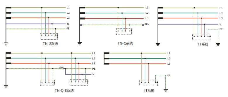
The protection mode of power SPDs needs to be selected based on the type of power system. There are several types:
The first letter indicates the grounding condition of the power system, where T represents direct grounding and I represents no grounding or grounding through high-impedance.
The second letter indicates the grounding condition of the exposed conductive parts of the device (represented by a dashed box). N represents grounding via the power supply grounding point, T represents direct grounding without using the power supply grounding point, and C (combination) represents a combination of N and PE.
S (separation) indicates the separation of N and PE.

In a power system, neutral line N carries current, especially during unbalanced voltages in a three-phase system.
In TN-S system, N and PE are separated. There is current on the N line, while the PE line has no current, making it safer. In the TN-S system, N and PE are only connected at the neutral point of the transformer, and N should not be grounded multiple times, while PE can be grounded multiple times. Therefore, SPDs are also installed between N and PE. TN-S system is the most widely used power distribution system. Both GB50057 and GB50343 mention: "When the power supply adopts the TN system, the power supply to the distribution and branch circuits within the building from the main distribution box must use the TN-S system."
In TN-C system, N and PE are combined, so this method is not very safe and not suitable for places where people are present for extended periods.
TN-C-S system combines TN-C system in the first half and TN-S system in the second half, balancing cost and safety.
TT system has separate grounding for the power side and the device side. Compared to TN-S system, TT system requires one less PE wire, resulting in lower costs. In TT system, when a device has a ground fault, the fault voltage does not propagate along the PE or PEN wire to other devices. Therefore, it is often used in outdoor installations where equipotential bonding is not convenient.
IT system does not have grounding at the power source. In the event of a phase-to-ground fault, since the power source end is not grounded, a fault current circuit cannot be formed. The fault current is minimal, and the fault voltage to ground is low, preventing accidents and power interruption. IT system is suitable for electrical devices that require uninterrupted power supply. However, due to the lack of a neutral line, it can only provide three-phase power and cannot supply single-phase devices. SPD selection should correspond to the type of power system. For example, 4P SPD is chosen for TN-S system.
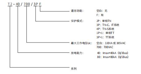
Naming conventions for AC power SPDs (T-series example):

As a leading SPD manufacturer, we offer comprehensive solutions for the configuration, selection, and protection modes of power surge protective devices, ensuring optimal protection against electrical surges.